The antennas are a key component for any radio link solution and the same for radio waves are applicable here. The right combination depends on the objectives, like short-range (all-around flight) or long-range flight for more advanced pilots. A good starting point is the default antennas for the wifi cards at the workbench (omnidirectional), once you get confident with the system during a line of sight and short flights, you can move with directional antennas.
As nothing is free, changing your antennas is a trade-off, while omnidirectional antennas give you autonomy to fly around your position, these antennas offer limited range, on the other side directional antennas concentrate the radiated pattern and allow a long-range at the cost of the need of pointing the antennas precisely, in other words, more antenna gains more directional. For the high directive antenna, add components like trackers are recommended to keep always pointing the main antenna pattern lobule to the aircraft.
The below link explains how the video quality is impacted under different scenarios. https://www.youtube.com/watch?v=T78JRAELjec
*Links are only for reference purposes. It will be added more as users report, check the connector type in order to make sure it will fit to your wifi card.
A typical question is related to the maximum range, link budget or system range have relation to three main elements: Transmitter power, Antenna gains, and Receiver sensitivity. The next formula can be used to calculate this:
R_km = 10 ^ ( ( RF_HW - LM - 32.44 - 20*log10(f_MHz) ) / 20 )
RF_HW = P_TX + G_TX + G_RX - S_RX
where:
R_km is the transmission range in km
f_MHz is the frequency in MHz
LM is the desired system Link Margin in dB
32.44 is the Friis constant for solving with units of km and MHz above
RF_HW represents the RF Hardware (Radio / Antenna) parameters in dB
P_TX is the Tx power in dBm
G_TX is the Tx antenna gain in dBi
G_RX is the Rx antenna gain in dBi
S_RX is the Rx Sensitivity in dBm
*Network card receiving sensitivity approx. -93dBm. Link margin assumed 10 dB
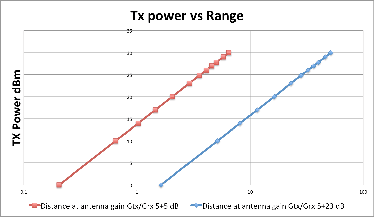
To understand the impact in range against the transmitter power, the below logarithmic graph shows some calculations using different antenna sets: